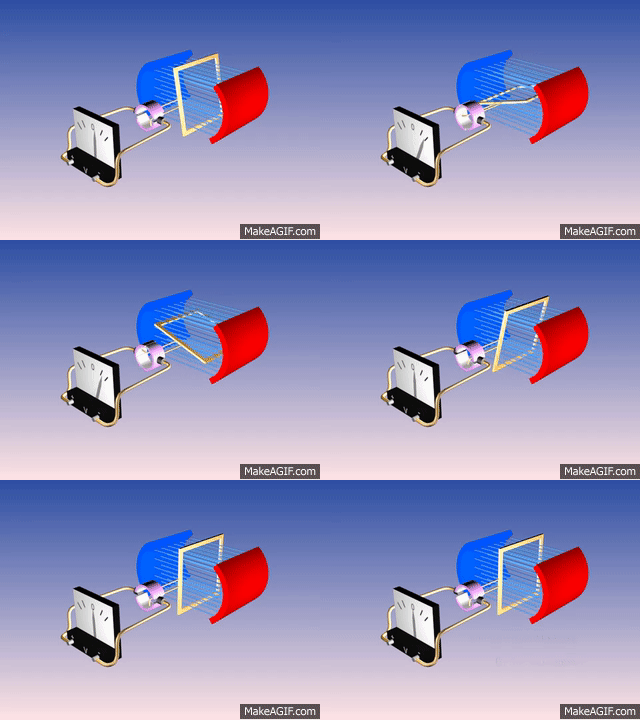
All we need to do to use the device in our aircraft is to change the AC to direct current DC so it can charge our battery. In a generator it is controlled by how the windings are wound in the coil, and in an Alternator it is done using diodes. (A diode is a semiconductor that allows current to flow in only one direction)
To control the field coil we use a Regulator that measures the voltage coming out of the unit and when it gets too high it reduces the magnetic field and if it is too low it increases the magnetic field.
This increase/decrease happens quite quickly so a steady 12.0 to 13.5 VDC is seen on a volt meter.
Shown above is a typical Cessna alternator charging system schematic.
Let's look at the regulator. Normally they have 3 leads: the Field (F); Alternator (A)/Battery (B); System On-Off (S), Ignition(I)
Sometimes they will be labeled a little different so consult the regulator manufacture's diagram if you are unsure.
Field: This wire gets energized when the regulator is on.
Alternator: This is the connection the regulator uses to sense the voltage output of the alternator. Too high, field is reduced, too low, field is increased.
System On-Off. This gets energized when the master switch is turned on which activates the regulator.
Before diving deep into troubleshooting your pesky charging system, do an overall inspection, checking wire condition, wire lugs for corrosion, tighten all terminals, etc.
To quickly troubleshoot your Generator/Alternator system refer to this chart. Troubleshooting Flow Chart
- If your aircraft is equipped with a split master switch then the alternator switch should be off when starting the engine. Once engine is running at idle you can turn the switch on.
- If you are replacing your existing generator with a new Alternator/Regulator system with an over voltage protection circuit, be aware that some Cessnas have one already built in that is buried in the wiring harness. You must find it and remove it before installing the new Alternator system.
